E-mail: [email protected]
E-mail: [email protected]Address: NO. 132 Xingye Road,Fengqiao Town ,Zhuji City,Zhejiang
Whatsapp: +86-13958007768
Whatsapp: +86-13655857582




Need Help
+86-13958007768
E-mail: [email protected]
E-mail: [email protected]
Address: NO. 132 Xingye Road,Fengqiao Town ,Zhuji City,Zhejiang
Whatsapp: +86-13958007768
Whatsapp: +86-13655857582
Our team is proud to offer on time guarantee and product guarantee to customer satisfaction.
Read MoreNews
 Home / News / Industry News / Optimizing Fleet Efficiency: The Technical Mechanics and Maintenance of Modern ECAS Valves
  2026.05.28
 Industry News
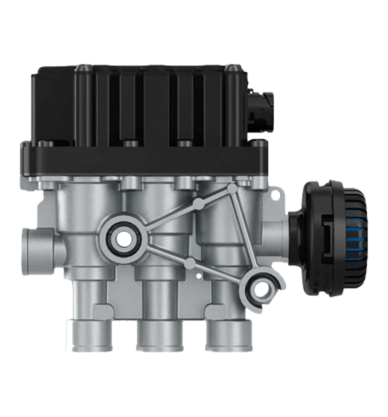
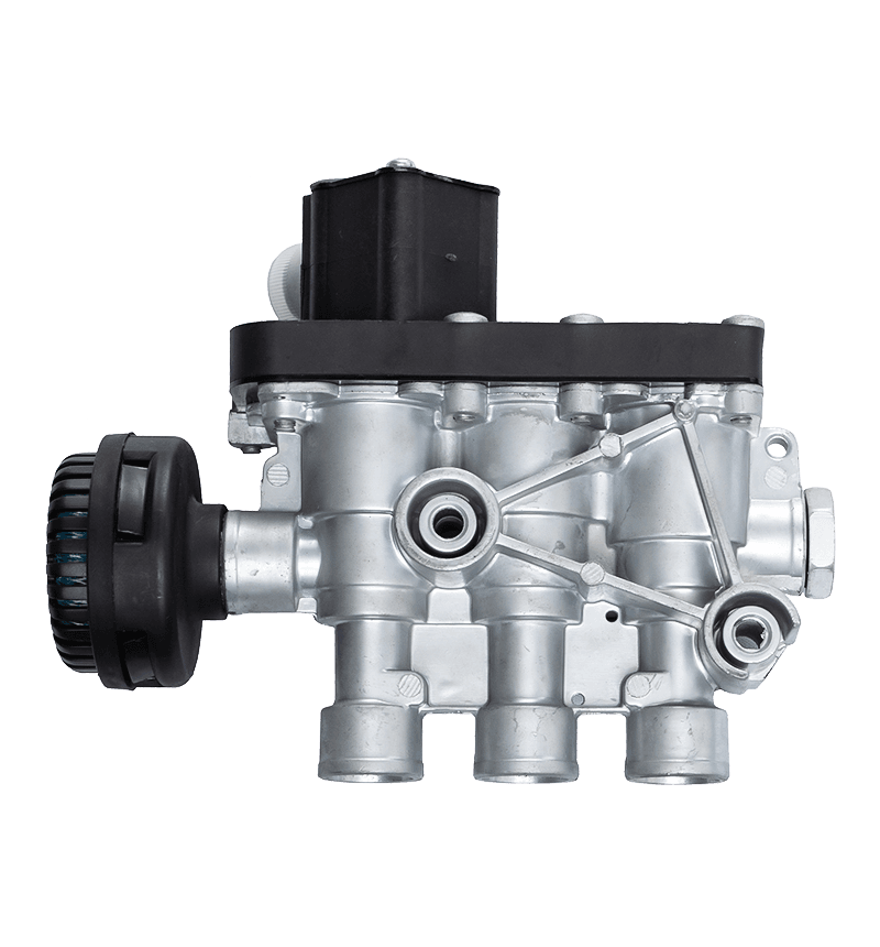
Modern commercial transportation requires dynamic adaptation to changing payload masses, road surface anomalies, and aerodynamic conditions. The ECAS valve (Electronically Controlled Air Suspension valve) serves as the primary pneumatic actuator within advanced chassis leveling systems, dictating exactly how air is distributed to or exhausted from a vehicle's suspension bellows. By replacing older mechanical leveling valves with precise, fast-acting solenoid arrays, this component minimizes compressed air consumption, stabilizes ride heights, and optimizes vehicle handling under extreme freight loads.
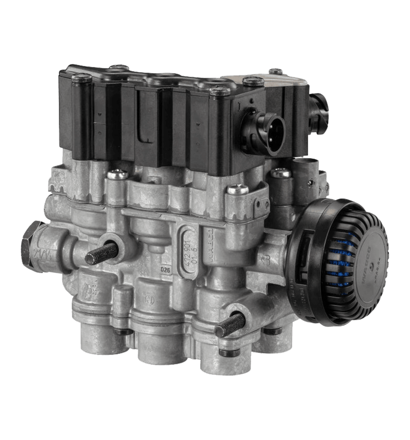
An ECAS valve is essentially an integrated manifold containing high-speed, pulse-width modulated (PWM) solenoids housed within a robust aluminum or composite body. Unlike mechanical leveling valves that continually adjust over every bump—wasting massive amounts of compressed air—the electronic valve operates only when verified by an electronic control unit (ECU). The unit filters out temporary suspension deflections caused by road irregularities, responding instead to sustained changes in chassis position.
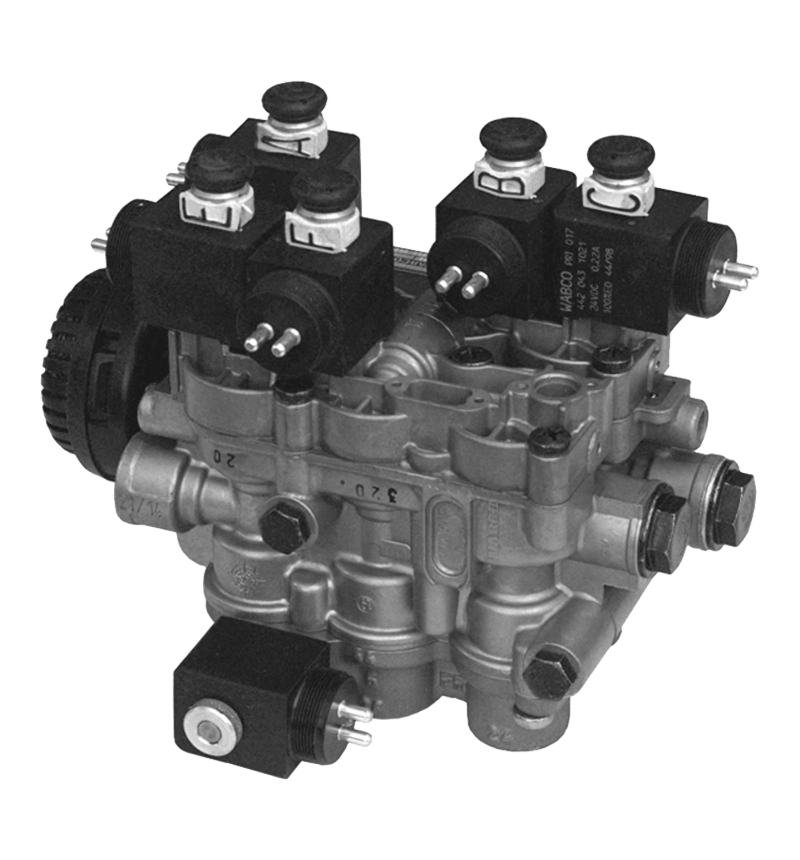
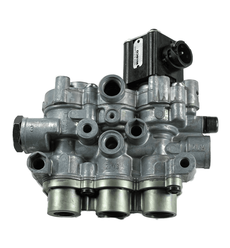
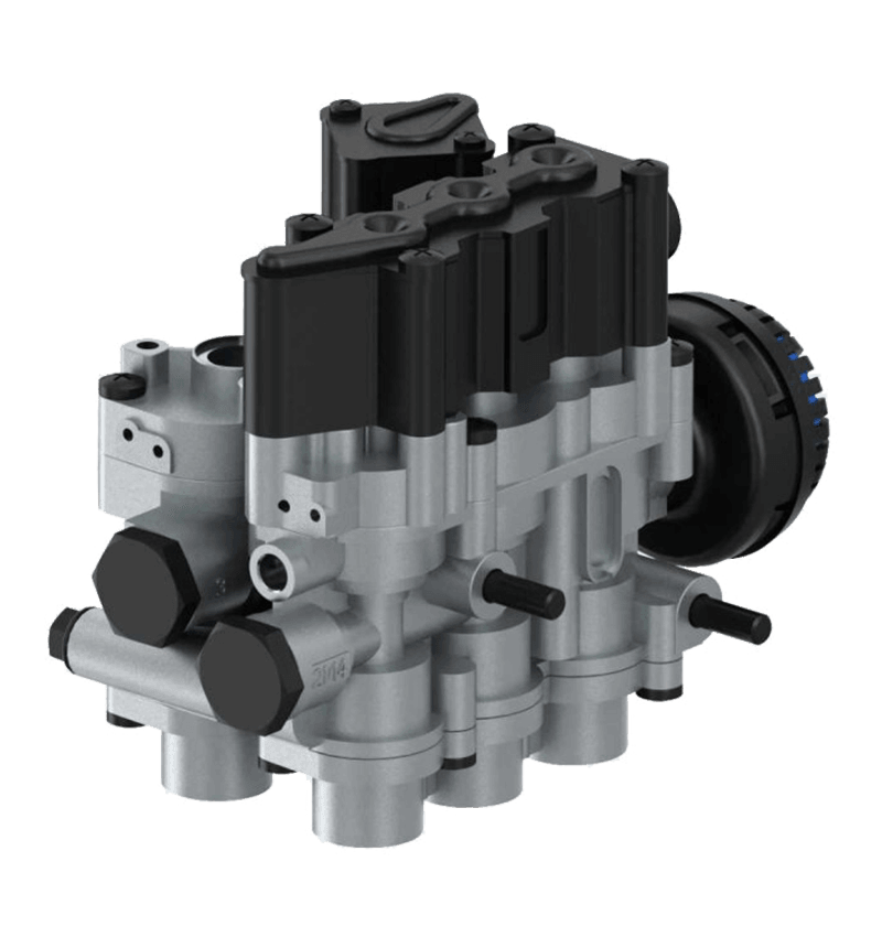
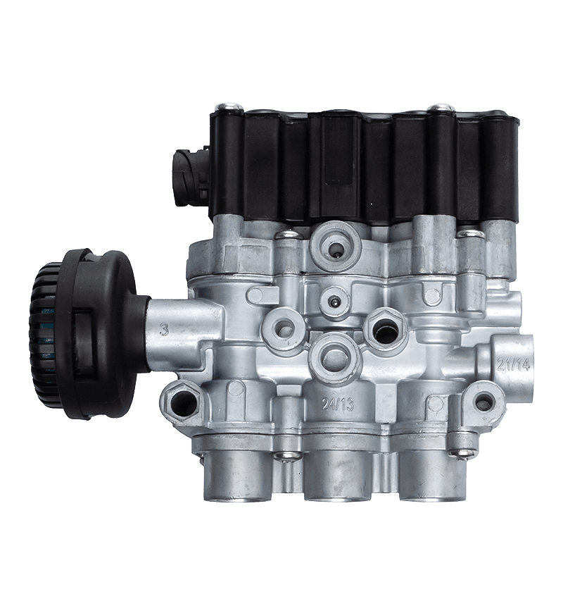
The valve assembly contains specialized internal channels that guide air via distinct functional sections. An intake solenoid manages incoming pressurized air from the primary chassis reservoirs, while an exhaust solenoid vents air into the atmosphere to lower the frame. Distribution solenoids route this air selectively to the left or right air springs, allowing the system to correct lateral imbalances caused by unevenly distributed cargo.
When the ECU commands a height change, a 24-volt electrical current energizes the internal copper wire coils. This creates a magnetic field that lifts a steel armature or plunger off its rubber seat against an internal return spring. This movement opens the pneumatic seat within milliseconds, allowing air to flow rapidly through the valve to either raise or stabilize the suspension.
The ECAS valve does not operate in isolation; it functions within a highly integrated closed-loop electronic network. Inductive or Hall-effect height sensors mounted between the vehicle frame and axles constantly measure the distance between the chassis and the ground, translating this physical distance into an electronic signal.
The ECU processes these sensor readings multiple times per second. If a heavy pallet is loaded onto the rear of a truck, the height sensors register a drop below the programmed nominal ride height. The ECU evaluates this signal over a pre-programmed time delay—typically 1 to 3 seconds—to confirm it is a true load change rather than a temporary dip in the road. Once verified, the ECU sends an electrical signal to the ECAS valve's inlet and supply solenoids, introducing compressed air into the bellows until the sensors confirm the vehicle has returned to its optimal ride level.
When navigating high-speed curves, centrifugal forces cause air to shift within the suspension system. A major advantage of an electronic suspension valve over older systems is its ability to seal off the left and right air bellows from one another. By isolating these circuits during cornering, the valve prevents air from transferring from the high-pressure loaded side to the low-pressure unloaded side, substantially reducing body roll and improving vehicle safety.
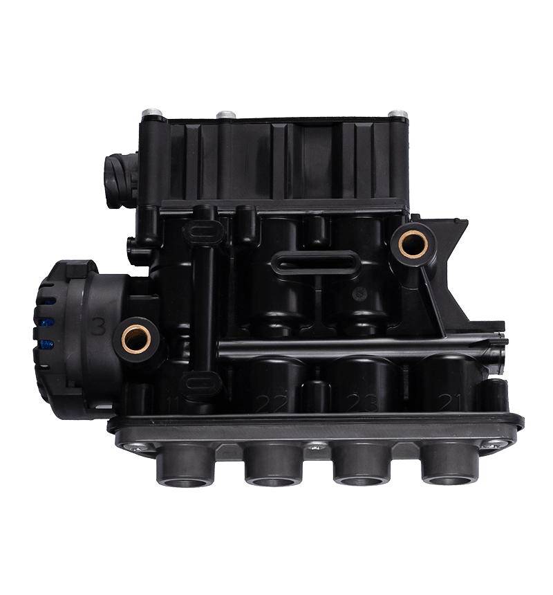
To ensure proper system pressure management and prevent line routing mistakes during service replacement, ECAS valves utilize standard pneumatic port identification numbers cast directly into the valve housing.
The following table outlines the technical specifications, standard operating pressures, and port designations for a typical dual-circuit commercial vehicle ECAS valve assembly:
| Port Designation | Pneumatic Function | Thread Connection Size | Max Operating Pressure | Electrical Connector Type |
|---|---|---|---|---|
| Port 1 | Supply Air Input (from tank) | M16 x 1.5 | 13.0 bar (188.5 psi) | Bayonet DIN 72585 |
| Port 21 | Delivery to Left Air Bag | M12 x 1.5 | 10.0 bar (145.0 psi) | Integrated Pin Housing |
| Port 22 | Delivery to Right Air Bag | M12 x 1.5 | 10.0 bar (145.0 psi) | Integrated Pin Housing |
| Port 3 | Atmospheric Exhaust Vent | Integrated Silencer | N/A | N/A |
Because ECAS valves are mounted underneath the vehicle chassis, they are exposed to harsh conditions, including road debris, pressure washers, extreme temperatures, and chemical de-icers. Understanding how these elements cause specific failure modes helps minimize troubleshooting time.
Internal solenoid coils are vulnerable to thermal cycling and moisture intrusion. If the protective plastic housing cracks, salt-laden road spray can seep into the coil winding, causing an internal short circuit or open circuit fault. This triggers an immediate suspension fault code on the dashboard dashboard display. Technicians can diagnose this by using a digital multimeter to measure the resistance across the valve pins; a healthy 24V coil should register a steady resistance value between 15 and 85 ohms depending on the exact design layout. A reading of zero ohms indicates a complete short circuit, requiring a valve replacement.
If a fleet's air dryer maintenance schedule is neglected, oil vapor and water can slip past the filtration system and reach the ECAS manifold. This contamination breaks down the factory grease on the internal valve seats and causes the internal rubber sealing discs to swell or deform. As a result, the valve may leak air out of the exhaust port (Port 3) when it should be holding pressure, causing the vehicle's suspension to sag or "leak down" overnight when parked.
In cold climates, moisture trapped inside the air lines can freeze directly inside the ECAS valve channels. This ice physically locks the internal plungers in place, preventing them from moving when the solenoid coil is energized. This issue often presents as a suspension system that works perfectly in a warm shop but fails completely when operating in sub-zero winter environments.
Implementing a proactive preventative maintenance schedule helps prevent unexpected on-road failures, protecting both the vehicle's cargo and components further downstream.
When replacing a faulty ECAS valve, installing the new hardware is only part of the repair process. Because the valve relies on precise signals from the height sensors, the entire system must be electronically recalibrated using specialized diagnostic software connected to the vehicle's OBD port.
To perform this calibration, park the vehicle on a perfectly level service bay floor. Using the diagnostic software, manually actuate the new ECAS valve solenoids to inflate and deflate the air springs until the chassis matches the manufacturer's exact ride height specifications, measured directly from the center of the axle hub to the frame rail. Once these measurements are confirmed, save these target values into the ECU's non-volatile memory. This calibration establishes the new baseline that the ECAS valve will work to maintain during real-world fleet operations.
 NO. 132 Xingye Road,Fengqiao Town ,Zhuji City,Zhejiang
 +86-13958007768 +86-13655857582
Copyright © Zhuji Infia Auto Parts Co., Ltd. All Rights Reserved.
Wholesale Truck/Bus Brake Parts Suppliers
 English
 Español