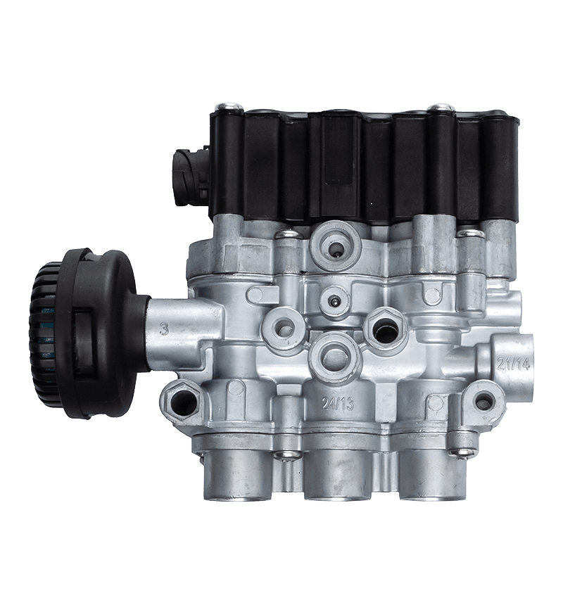
Understanding the Function of Gearbox Valves in Mechanical Systems
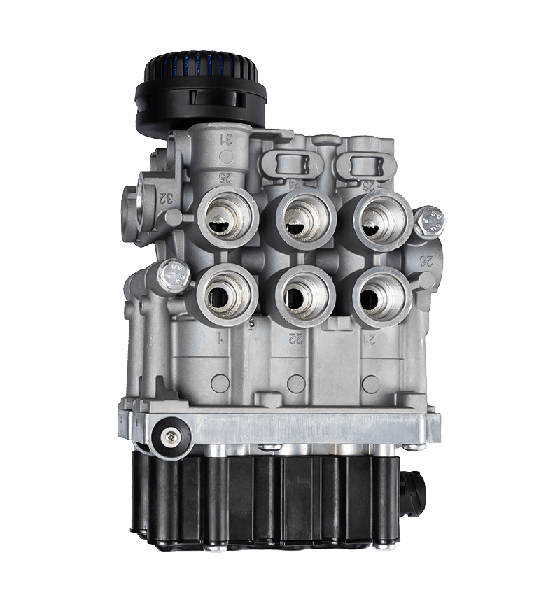
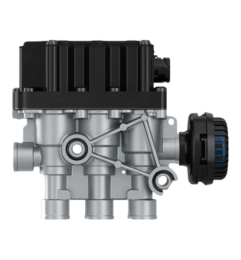
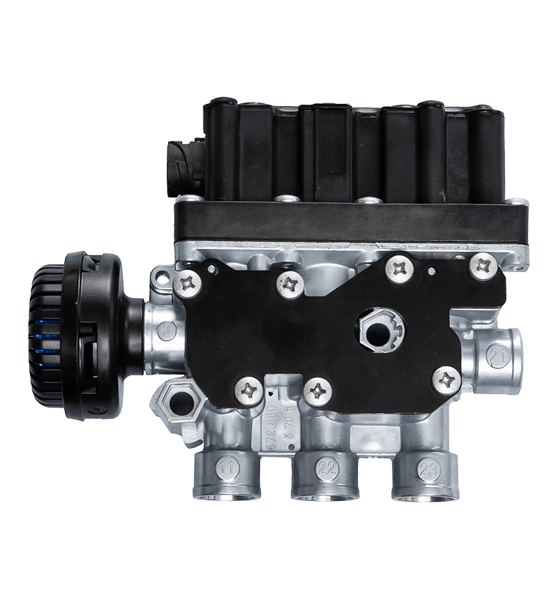
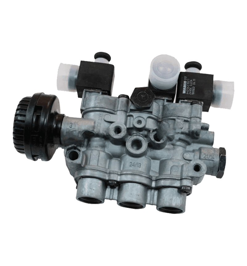
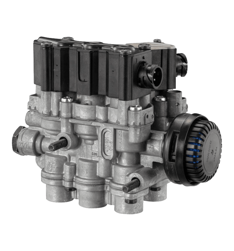
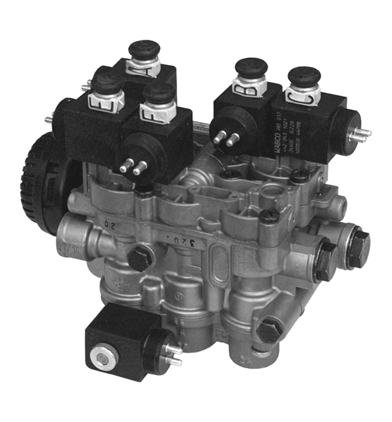
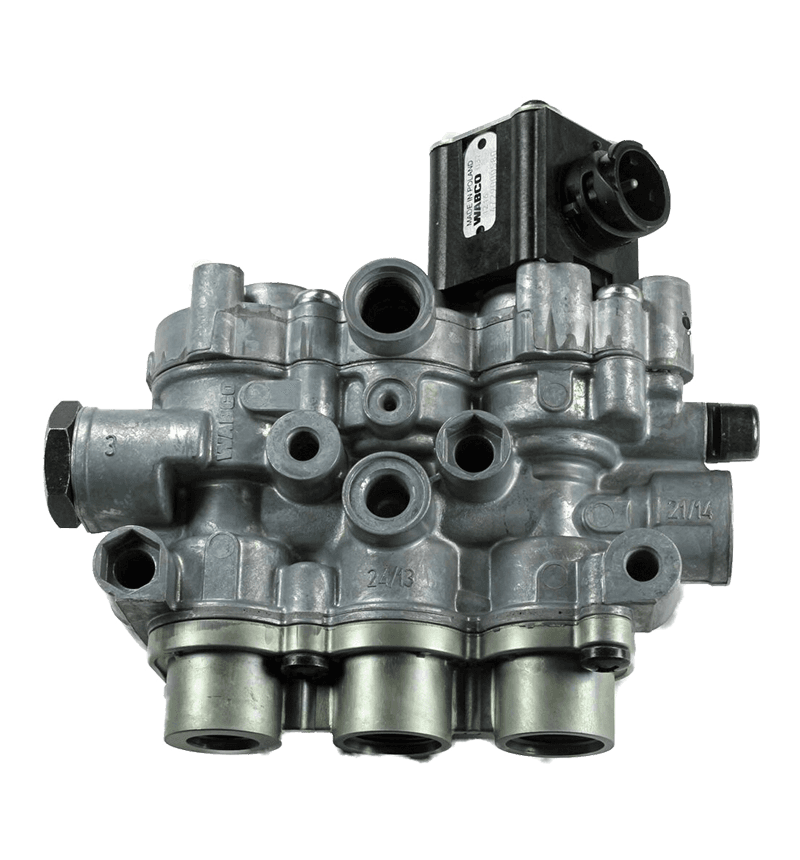
Gearbox valves play an important role in controlling fluid flow and pressure in both industrial equipment and hydraulic transmission systems. They function as control components that regulate the transfer of hydraulic oil or lubricating fluid within gear mechanisms. By managing fluid direction and maintaining balanced pressure levels, gearbox valves ensure smooth torque transmission, minimize energy loss, and enhance system stability. In complex industrial machinery, these valves contribute to load management and gear shifting precision, making them indispensable for modern hydraulic and mechanical systems.
Structural Characteristics of Gearbox Valves
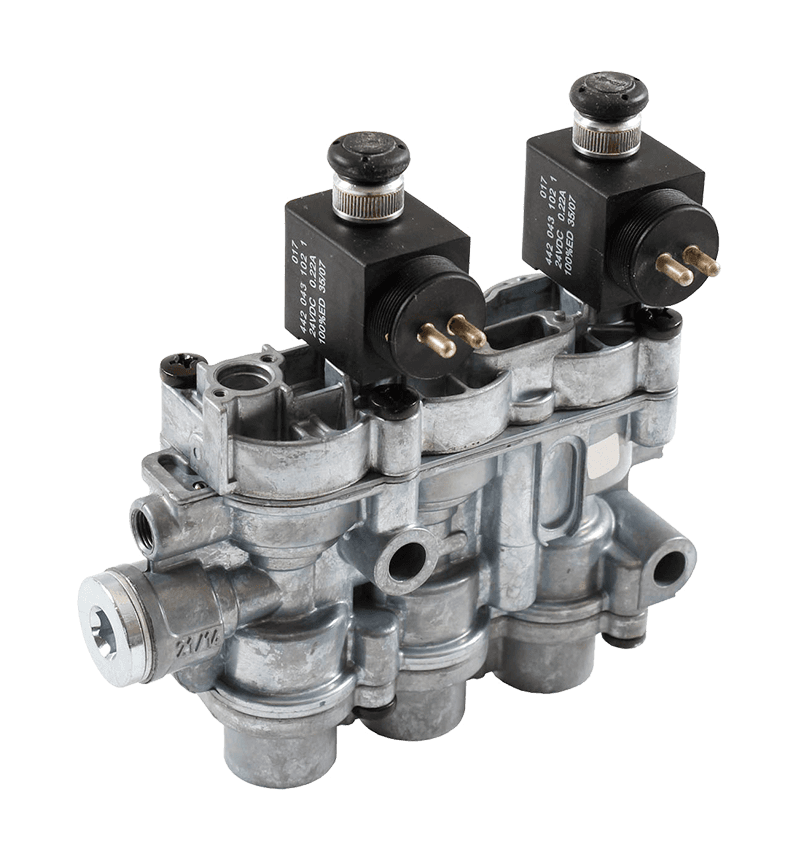
The structure of gearbox valves typically includes a valve body, spool or poppet, sealing components, and actuation mechanisms such as springs or solenoids. The materials used for these components are selected based on their mechanical strength, wear resistance, and corrosion resistance, as gearbox environments often involve high pressure and temperature fluctuations. Precision machining is required to achieve tight tolerances that prevent internal leakage and maintain consistent flow characteristics. In hydraulic transmission systems, the valve’s internal pathways are optimized for minimal turbulence, ensuring efficient fluid movement even under variable load conditions.
Application in Industrial Equipment
In industrial machinery, gearbox valves are commonly found in systems where precise motion control and torque transmission are essential. Equipment such as heavy-duty presses, conveyor drives, cranes, and machine tools utilize these valves to regulate hydraulic pressure and direction during operation. Gearbox valves enable consistent lubrication and prevent mechanical wear by ensuring continuous oil circulation. They also help manage temperature rise by maintaining fluid flow balance within the gear housing. The controlled pressure flow provided by the valve system enhances energy efficiency, reduces frictional loss, and ensures reliable power delivery across rotating components.
Role in Hydraulic Transmission Systems
Hydraulic transmission systems rely heavily on gearbox valves for efficient energy conversion and motion control. These systems use pressurized hydraulic fluid to transfer mechanical energy between components such as pumps, motors, and cylinders. Gearbox valves in this context regulate fluid direction, manage overload protection, and facilitate smooth gear shifting. Proportional and servo-controlled valves are often used in high-precision systems, allowing for adjustable flow rates according to operational needs. Proper valve performance ensures consistent transmission response, stability under variable loads, and reduced vibration or noise in the hydraulic system.
Comparison Between Mechanical and Hydraulic Applications
While gearbox valves serve similar control purposes in both mechanical and hydraulic systems, their functional parameters and design priorities differ. Mechanical applications emphasize lubrication and cooling efficiency, whereas hydraulic systems focus on pressure regulation and directional control. The following table summarizes key differences between these two applications.
| Application Type |
Main Function |
Operating Medium |
Key Design Consideration |
Typical Usage |
| Mechanical Gearbox |
Lubrication and flow management |
Lubricating oil |
Temperature and viscosity control |
Industrial gearboxes, drive systems |
| Hydraulic Transmission |
Pressure and directional control |
Hydraulic oil |
Flow precision and responsiveness |
Hydraulic motors, pumps, actuators |
Material Selection for Gearbox Valve Manufacturing
Material choice is crucial to ensure reliability under demanding working conditions. Gearbox valves are commonly made from high-strength steels, aluminum alloys, or brass, depending on the pressure and temperature requirements. Stainless steel is often selected for its corrosion resistance and mechanical stability. In hydraulic systems exposed to corrosive fluids or moisture, specialized coatings such as nickel plating or nitriding are applied to enhance surface durability. The sealing materials—typically fluororubber, PTFE, or nitrile—must maintain elasticity and tightness across varying temperatures and pressures to prevent internal leakage.
Performance Requirements and Testing Standards
To ensure consistent quality, gearbox valves undergo multiple testing procedures before being integrated into equipment. These include leakage tests, flow rate calibration, pressure endurance evaluation, and temperature stability assessment. International standards such as ISO 10770, DIN 24342, and SAE J514 are often referenced during design and validation stages. Proper testing guarantees that the valve operates efficiently under real working conditions, avoiding performance degradation due to fatigue or material deformation. Functional reliability under repeated load cycles is particularly critical for industrial applications that run continuously.
Thermal Stability and Fluid Compatibility
Gearbox valves must maintain functionality even when exposed to high thermal environments caused by friction and hydraulic pressure. The design includes thermal-resistant components and adequate spacing to accommodate expansion. In hydraulic systems, compatibility with different types of hydraulic oils—including mineral-based, synthetic, or biodegradable fluids—is essential. Selecting the correct valve design ensures that seals and internal surfaces remain stable without chemical reactions or swelling. Proper fluid compatibility not only prevents leakage but also maintains consistent control performance across a wide temperature range.
Influence of Flow Characteristics on System Efficiency
Flow dynamics within gearbox valves directly affect energy efficiency and response speed. A well-designed valve minimizes flow restriction, turbulence, and pressure loss. Computational Fluid Dynamics (CFD) simulation is often employed during design to optimize internal geometries for laminar flow. Smooth fluid transition across valve ports allows for precise control of actuation speed in hydraulic systems. In industrial gearboxes, steady oil circulation ensures effective heat dissipation and wear reduction. Both functions—flow stability and energy conservation—are vital for maintaining long-term operational efficiency.
Integration with Control Systems
Modern gearbox valves are frequently integrated with electronic control systems to achieve automatic pressure adjustment and real-time monitoring. Proportional and servo valves respond to electrical signals that vary flow or pressure according to sensor feedback. This allows adaptive performance across different operating conditions. In industrial automation, integration with PLC (Programmable Logic Controller) systems enables precise synchronization between hydraulic and mechanical components. Electronic monitoring of valve behavior helps detect potential issues early, improving maintenance efficiency and minimizing unplanned downtime.
Maintenance and Service Life Considerations
Routine inspection and maintenance are vital for sustaining the performance of gearbox valves. Maintenance tasks typically include cleaning valve channels, checking seals for wear, and monitoring for internal leakage. Replacing seals and lubricants at regular intervals helps prevent frictional damage. In hydraulic systems, contamination of the oil can lead to valve blockage or spool sticking; therefore, filtration systems must be properly maintained. Scheduled maintenance based on operational hours rather than failure occurrence extends valve service life and ensures reliable performance throughout the equipment’s operational cycle.
Safety Features and Overload Protection
Safety mechanisms integrated into gearbox valves prevent overpressure, sudden flow surges, or fluid backflow. Relief valves are often installed to automatically release excess pressure when system limits are exceeded. Check valves maintain one-way flow, protecting sensitive components from reverse pressure. In high-power hydraulic transmission systems, fail-safe mechanisms allow the valve to return to a neutral position during power loss, avoiding sudden mechanical shocks. These safety features are crucial in ensuring operational stability, particularly in systems handling large loads or continuous operation.
Environmental Adaptability and Corrosion Resistance
Industrial environments often involve exposure to humidity, temperature fluctuations, and chemical agents. Gearbox valves designed for such conditions require corrosion-resistant materials and protective coatings. Anodized aluminum, stainless steel, or coated steel surfaces resist rust and oxidation. In outdoor or marine applications, additional sealing protection prevents water ingress and particulate contamination. Environmental adaptability ensures that gearbox valves maintain functional integrity, even under challenging conditions, making them suitable for a wide range of industrial and hydraulic applications.
Comparison of Valve Types Used in Gearbox Systems
Different valve types are used within gearbox and hydraulic transmission systems, depending on the operational requirements. The table below summarizes several common valve types and their primary applications.
| Valve Type |
Function |
Control Mode |
Application |
| Pressure Relief Valve |
Limits system pressure to prevent overload |
Mechanical or hydraulic |
Industrial hydraulic circuits |
| Directional Control Valve |
Controls flow direction |
Manual or solenoid |
Hydraulic gear shifting systems |
| Check Valve |
Prevents reverse flow |
Automatic |
Lubrication and hydraulic transmission |
| Flow Control Valve |
Regulates flow rate |
Manual or electronic |
Speed control in hydraulic drives |
Integration with Modern Hydraulic Power Units
Gearbox valves are key components in hydraulic power units (HPUs), which supply pressurized oil to actuators or gear assemblies. In integrated systems, valves coordinate pressure distribution, temperature control, and circuit safety. Modern HPUs often employ modular valve blocks, where multiple functions are combined into a single assembly to save space and improve serviceability. Smart control interfaces allow operators to monitor system performance, including valve position, flow rate, and temperature. Such integration enhances precision and simplifies complex control tasks across various industrial operations.
Innovations and Technological Advancements in Valve Design
Recent advancements in valve technology focus on improving response time, energy efficiency, and environmental compatibility. Lightweight designs using composite materials help reduce overall system weight without sacrificing durability. Advanced sealing technologies, such as double-lip seals and low-friction coatings, improve fluid retention and minimize leakage. Electromechanical valves equipped with integrated sensors enable predictive maintenance by transmitting operational data for real-time analysis. The combination of mechanical engineering and digital monitoring leads to higher operational reliability and greater adaptability in both industrial and hydraulic transmission systems.
Cost and Efficiency Balance in Gearbox Valve Selection
When selecting gearbox valves, manufacturers must balance cost efficiency with performance and durability. High-precision valves with electronic control capabilities may have higher initial costs, but they provide long-term savings through reduced maintenance and energy consumption. Conversely, simpler mechanical valves may suffice for systems with lower performance demands. A proper evaluation based on pressure range, fluid type, temperature conditions, and response requirements ensures optimal valve choice for specific applications. The table below outlines general cost-to-performance relationships among common valve configurations.
| Valve Type |
Relative Cost |
Control Precision |
Maintenance Frequency |
| Mechanical Valve |
Low |
Basic |
Regular |
| Hydraulic Valve with Relief Function |
Medium |
Moderate |
Occasional |
| Proportional Valve |
High |
High |
Low |
| Servo Valve |
Very High |
Very High |
Low |
Conclusion on Suitability for Industrial and Hydraulic Applications
Gearbox valves are well-suited for both industrial equipment and hydraulic transmission systems due to their ability to regulate flow, manage pressure, and enhance operational safety. Their adaptability to diverse working environments, combined with technological progress in material science and electronic control, has made them indispensable in modern automation and machinery. Through careful design, proper material selection, and maintenance, these valves continue to support efficient and reliable performance in industrial and hydraulic applications worldwide.


 English
 Español


